
In software development, a bug is just a Jira ticket that gets fixed in 30 minutes. In electronics (Hardware), a bug costs $100+ for a new batch of boards, two weeks of waiting for delivery, and a day of desoldering components under a microscope.
Most mistakes—both "rookie" errors and those made by pros—can be caught before you export the Gerber files. You don't always need expensive simulators for this; often, attentiveness and basic physics are enough.
Here are 5 problems that most often kill the first revision of a board, and how to avoid them.
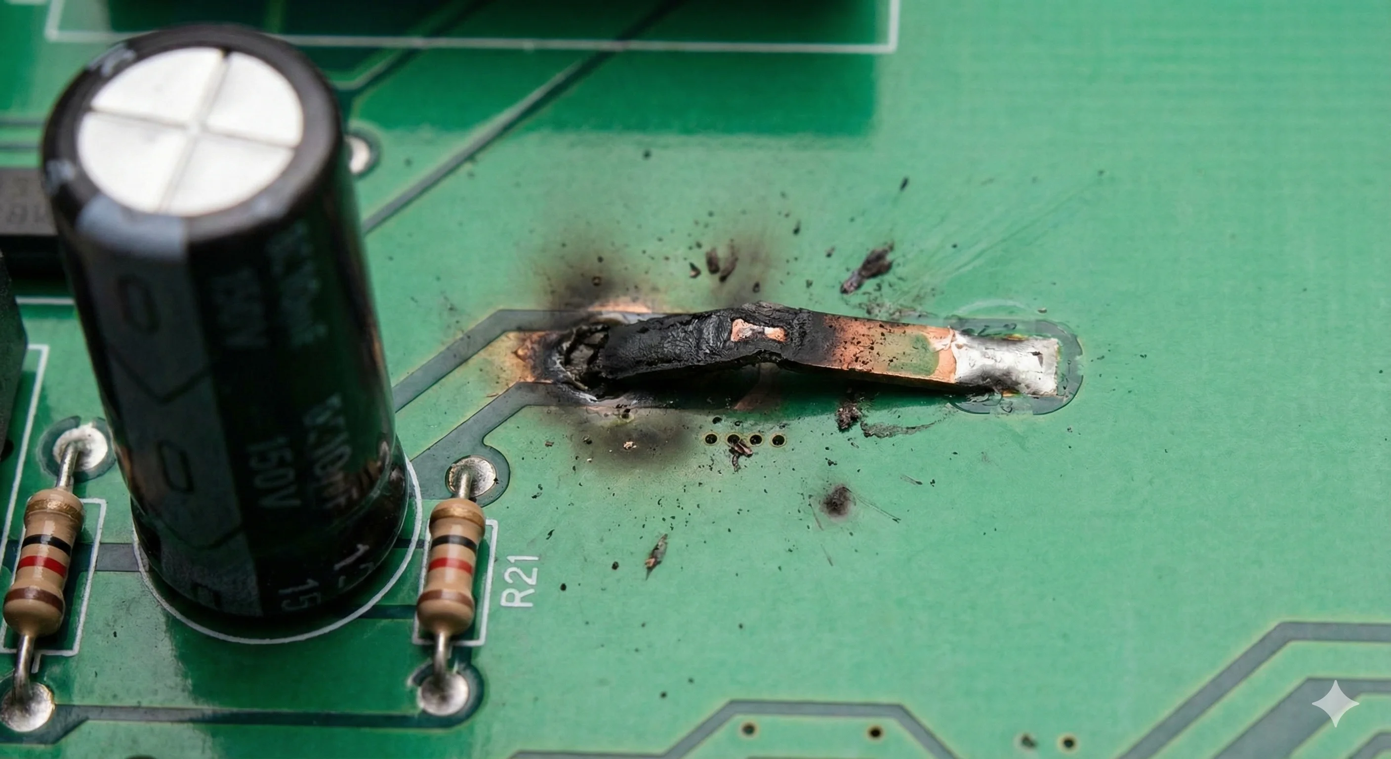
"The Trace Burned Out" (Insufficient Power Trace Width)
The Problem: You are routing a board and, out of habit, draw the power line (VCC) with the same width as the signal lines (e.g., 0.2 mm). But if a current of 2A needs to flow through this line (for example, for a GSM module or a servo), it turns into a fuse: it overheats and burns out.
How to avoid it: Don't rely on intuition ("it looks thick enough"). Always use trace width calculators (IPC-2221 standard).
Rule of Thumb: For an external layer with 1oz (35 µm) copper thickness, 1 Ampere requires approximately 0.3-0.4 mm of width (depending on the allowable temperature rise).
Tip: For power lines, it is better to use polygons (Copper Pours) rather than thin traces.
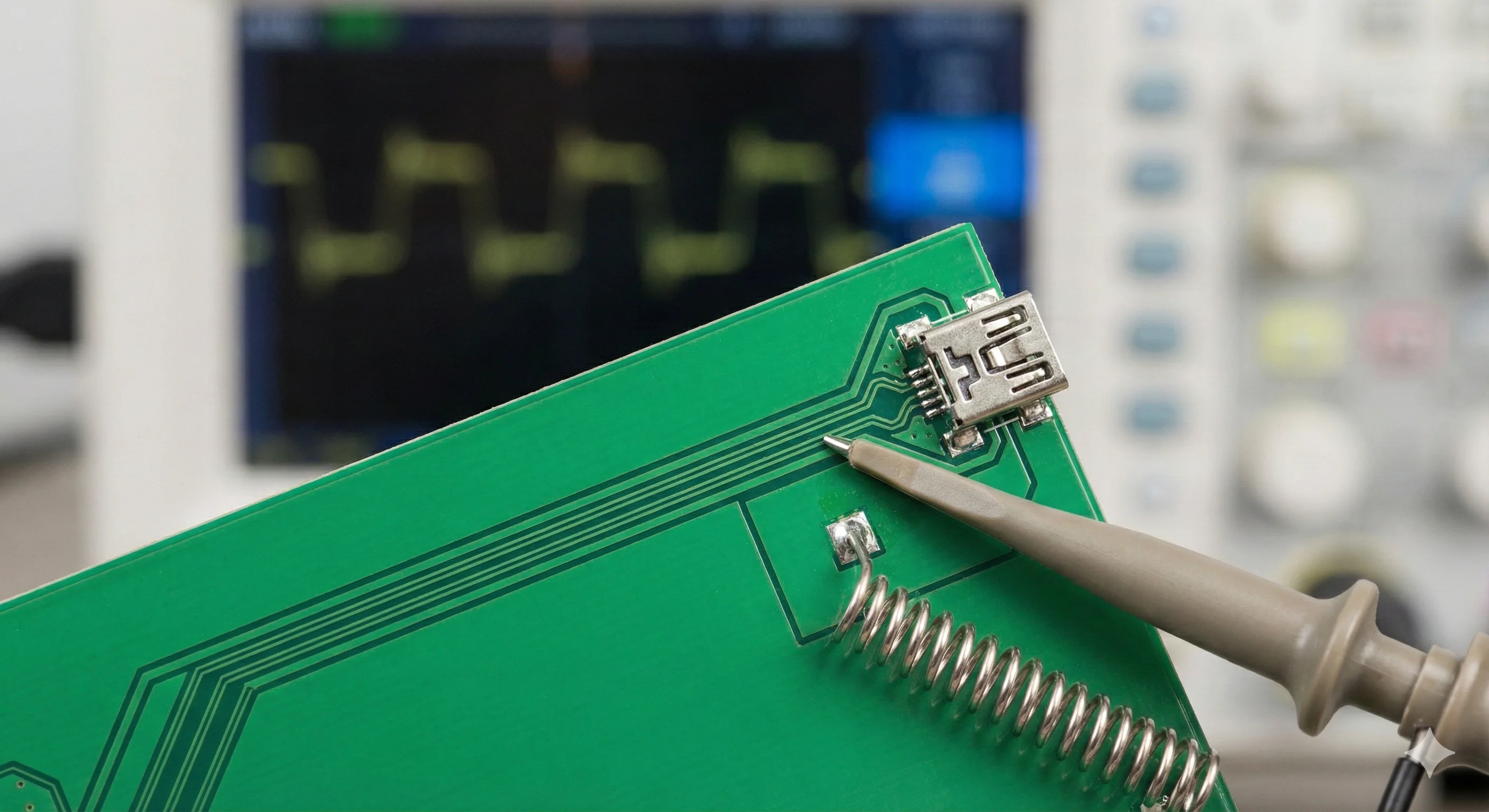
"Why is USB Unstable?" (Ignoring Impedance)
The Problem: You are routing USB, Ethernet, or connecting a Wi-Fi antenna. You connected the processor pin to the connector using the "shortest path," but the signal keeps dropping. The reason is signal reflection due to mismatched impedance.
How to avoid it: High-speed lines are not just conductors; they are waveguides.
Find out the stackup parameters from your PCB manufacturer (prepreg thickness, dielectric constant).
Calculate the geometry: differential pairs (USB D+/D-) usually require 90 Ohms impedance, and antennas require 50 Ohms.
Never break the ground plane (GND) underneath these lines.
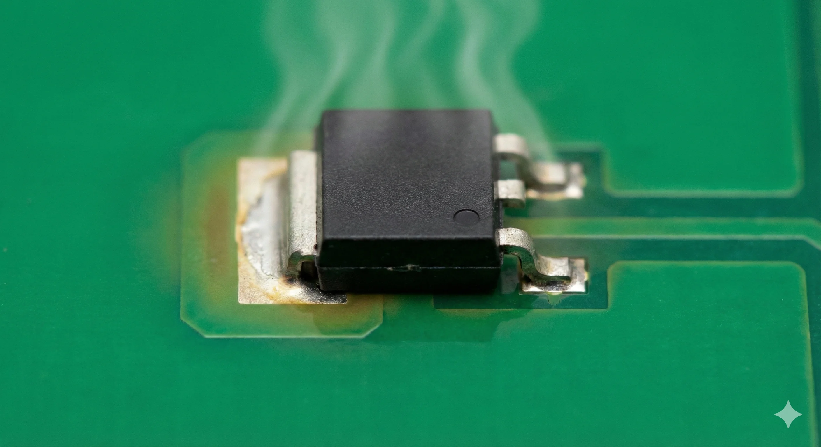
"The Regulator is Boiling" (Forgotten Thermal Management)
The Problem: You use a linear regulator (LDO), like the AMS1117, to step down 12V to 3.3V for a microcontroller. The current is only 200 mA, but the chip glows hot and shuts down.
The Physics: $P = (12V - 3.3V) \times 0.2A = 1.74 W$. A small SOT-223 package cannot dissipate that much heat into the air without help from the board.
How to avoid it:
Always read the "Thermal Resistance" section in the datasheet.
Create large copper pours around "hot" pins (usually GND or Tab).
Add thermal vias to the other side of the board to use its area as a heatsink.
Assembly Impossible (Mechanical Conflicts)
The Problem: The board arrives and looks great. You start soldering: the USB connector covers the mounting hole, a capacitor is too tall and hits the enclosure, and your screwdriver can't reach the terminal screw.
How to avoid it:
3D View is mandatory. Modern CAD tools (KiCad, Altium) have excellent 3D modes.
Export a STEP model of the board and fit it into the enclosure in a mechanical CAD tool (Fusion 360, SolidWorks).
Print the board layout on paper at a 1:1 scale before ordering—this is the cheapest way to verify component placement.
"I Thought You Fixed That" (Communication Chaos)
The Problem: This is the most expensive mistake because it is human. You work in a team. A colleague writes in Telegram: "Move capacitor C4 to the right" or "There is an error in the power routing." You open the project two days later, forget exactly which capacitor they meant, or look at the wrong version of the file. Result: the error goes into production.
How to avoid it: You need to eliminate the "game of telephone" and tie discussions directly to the schematic.
The Solution (using PCBHub as an example): Instead of screenshots in chats, you upload the project to the platform.
A colleague places a Point directly on the problem area of the schematic.
They write a comment: "This should be 10uF, not 100nF."
You see this marker right in the browser, fix it, and mark it as "Resolved" in the next version.
This transforms chaotic chats into a clear task list tied to visual context.
Conclusion
The magic of a successful hardware project isn't about never making mistakes, but about finding them cheaply—on a monitor screen, rather than in the smell of burnt fiberglass. Check your trace widths, watch the thermals, and most importantly, set up transparent communication within your team.